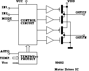
 |
|
- Small package (SOIC16)
- Current limitation Low power consumption
- Over temperature protection
- Direct microcontroller
compatible

Figure 1 |
The IC drives directly
small DC inductive or active loads like electric motors, lamps, etc.
There are four main driving modes. These are set by digital inputs "In1"
and "In2" :
|
In1 |
In2 |
M1 |
M2 |
Driving mode |
|
1 |
0 |
1 |
0 |
Forward |
|
0 |
1 |
0 |
1 |
Backward |
|
1 |
1 |
0 |
0 |
Brake (motor is shorted) |
|
0 |
0 |
Z |
Z |
Off (motor is disabled) |
The current of the output-drivers is limited for protection against all kind of overload and short-circuit conditions, and this in the whole supply voltage and temperature range.
The outputs "M1" and "M2" are on-chip diode-protected against motor inductances (Nominal values of 12mH and 12 Ohm).
If the temperature of the chip exceeds a preset value (selectable with the "Auto" pin), the temperature-overload protection-circuit disables the outputs, preventing the chip from being overheated. In addition, this socalled "temp ovl"-state is signalled with a low level at the "overtemp" pin.
Pinout
| Pin | Symbol | Function |
| 1 | M2 | Motor output 1 |
| 2 | VCC | Supply |
| 3 | n.c. | |
| 4 | GND | Ground |
| 5 | GND | Ground |
| 6 | n.c. | |
| 7 | VCC | Supply |
| 8 | M1 | Motor output 2 |
| 9 | IN2 | Control input 2 |
| 10 | IN1 | Control input 1 |
| 11 | n.c. | |
| 12 | VDD | Digital supply |
| 13 | OVERTEMP | Protection state output |
| 14 | GND Logic | Digital ground |
| 15 | n.c. | |
| 16 | AUTO | Protection setting |
Absolute Maximum Ratings
| Vcc | +16V |
| Maximum Output Current | 700mA |
| Die Temperature | +160�C |
| Storage Temperature | -55 �C to 125�C |
Electrical Characteristics
Following characteristics
are valid over the temperature range from -40�C to +85�C unless otherwise
specified.
Table 1
| Characteristics | Test Conditions |
Limits |
Units |
||
|
Min |
Typ |
Max |
|||
| Supply voltage VCC |
5 |
9 |
12 |
V |
|
| Supply voltage Vdd |
4.5 |
5.0 |
5.5 |
V |
|
| Mean motor current | Vcc=9V | 330 | mA | ||
| Vcc=6V | 300 | mA | |||
| Motor current limit | Vcc=9V |
550 |
mA | ||
| Vcc=6V | 500 | mA | |||
| Brake current | Vcc=9V |
240 |
mA |
||
| Vcc=6V |
180 |
mA |
|||
| Voltage drop at the output transistors |
Vcc=9V, Icc=300mA |
1.2 |
V |
||
| Vcc=6V, Icc=200mA |
1.2 |
V |
|||
| Supply current Icc | fwd, back, brake, temp ovl |
5.0 |
mA |
||
| off mode |
5.0 |
�A |
|||
| Supply current Idd | fwd, back, brake, temp ovl |
1 |
mA |
||
| off mode |
10 |
�A |
|||
| Inputs In1 & In2 | logic level |
TTL, |
V |
||
| Input "Auto" (Pull up) |
Current sourced (if tied to GND) |
25 | �A | ||
| Output 'overtemp' (open drain) |
temp ok output | HiZ | |||
| temp ovl output @ 1mA sink |
|
0.4 |
V |
||
Temperature Characteristics
Table 2
| Characteristics | Test Conditions |
Limits |
Units |
||
|
Min |
Typ |
Max |
|||
| Temp ovl protection turn on temperature |
Auto=1 or HiZ | 122 | Deg C | ||
| Auto=0 | 155 | Deg C | |||
| Temp ovl protection turn off temperature |
Auto=1 or HiZ | 93 | Deg C | ||
| Auto=0 | 105 | Deg C | |||
Typical Application Circuit

Figure 2 |
Last update of this page on Friday, August 18, 2000. Copyright � 1998-2000 Melexis. All rights reserved.